7 Best Ways to Maintain Consistent Lighting Performance

Time:2026-09-22 Author:Ethan
0%

Consistent lighting performance keeps rooms comfortable, products accurate, and visual work dependable. Yet brightness can drift quietly. A fitting may appear stable while its color shifts after hours of operation.

This guide explores How To Maintain Consistent Lighting Performance through seven practical methods. It considers fixture selection, scheduled cleaning, thermal control, electrical stability, and routine measurement. Each method connects daily maintenance with measurable results. A calibrated light meter can reveal uneven output across a work surface. Dust on a lens can also create visible shadows near the edges.

Small details matter.

Experienced facility teams often record illuminance, color temperature, operating hours, and replacement dates. These records support informed decisions instead of hurried repairs. Manufacturer guidance remains essential, especially for LED drivers, dimming systems, and ventilation clearances. Independent testing standards can also strengthen maintenance procedures and reduce guesswork.

However, no lighting plan is perfect. Sensors may require adjustment after furniture moves. Cleaning schedules may look suitable on paper but fail in dusty environments. Teams should review actual conditions and revise their approach when evidence changes. That practical honesty improves reliability.

The following seven strategies offer a clear framework for protecting lighting quality over time. They are designed for offices, retail spaces, workshops, and other environments requiring dependable illumination. With regular observation and disciplined maintenance, lighting can remain more stable, efficient, and visually consistent.
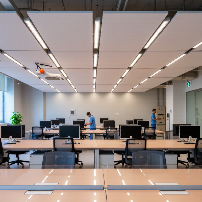
7 Best Ways to Maintain Consistent Lighting Performance

Define Illuminance Targets with IES RP-8 and CIE 115 Metrics

Consistent lighting begins with a measurable target, not a visual guess.

CIE 115:2010 defines CE lighting classes from 7.5 to 50 lux, depending on traffic, conflict areas, and environmental conditions. Select the class before choosing fixtures. Record the reason.

IES RP-8-18 also emphasizes maintained illuminance, uniformity, glare control, and veiling luminance. These metrics describe real performance after depreciation, not opening-day brightness.

A practical workflow includes seven checks: classify the road, set maintained illuminance, verify uniformity, model glare, account for dirt, measure aging output, and review seasonal results.

Field measurements should follow a fixed grid, with the same meter height and calibration record. Small errors matter.

CIE 115:2010 separates average illuminance from uniformity, so a bright average can still hide dark patches. That weakness is often missed. For example, a 20-lux average does not prove safe visibility if the minimum point falls sharply.

Use maintenance factors based on dust, operating hours, and cleaning intervals. Then compare measured values with the original design report. Professional lighting audits commonly find performance changes caused by dirt, control settings, or lamp aging rather than immediate equipment failure.

The data may disagree. Investigate before adjusting output, because excessive brightness can increase glare and energy use.

Maintain CCT Within ANSI C78.377 Bins and Color Shift Under 7 SDCM

Consistent lighting starts before assembly. Specify LED chromaticity within the ANSI C78.377 bins, not merely by nominal color temperature. Select sources with stable phosphor performance and review their test data carefully. Measure, do not assume. Use current regulation to prevent small electrical changes from altering output or color. A two-percent current difference can become visible across a large ceiling.

Thermal control is equally important. Keep junction temperatures stable with adequate heat paths, airflow, and contact pressure. Test the complete fixture, not only the LED package. Optical mixing chambers, diffusers, and suitable spacing can reduce visible color patches. Production checks should record CCT, flux, and chromaticity for every batch. Store those results.

Color shift must remain under 7 SDCM during operation and aging. Run thermal cycling, extended burn-in, and repeated on-off tests under realistic conditions. A fixture may pass at room temperature yet drift inside a warm enclosure. This has happened in field evaluations. Review the failure, then adjust the design rather than hiding the variation. Recheck samples after assembly, because adhesives, lenses, and soldering temperatures can influence final chromaticity. Clear limits, calibrated instruments, and traceable records make the result defensible.

7 Best Ways to Maintain Consistent Lighting Performance — Maintain CCT Within ANSI C78.377 Bins and Color Shift Under 7 SDCM

Practical quality-control framework for stable correlated color temperature (CCT), chromaticity, and long-term color consistency

No. Recommended Practice Control Dimension Suggested Acceptance Target Verification Method Relevant Reference
1 Specify the Correct ANSI C78.377 CCT Bin Nominal CCT and chromaticity coordinates on the CIE 1931 x, y diagram Select a recognized ANSI C78.377 nominal CCT such as 2700 K, 3000 K, 3500 K, 4000 K, 4500 K, 5000 K, 5700 K, or 6500 K. Keep production measurements inside the applicable ANSI quadrilateral. Measure each production lot with a calibrated spectroradiometer or integrating-sphere system. Record CCT, chromaticity coordinates, Duv, luminous flux, and power. ANSI C78.377, Specifications for the Chromaticity of Solid-State Lighting Products
2 Control LED Binning and Component Mixing LED package bin, nominal CCT, chromaticity, flux bin, and forward-voltage bin Use LEDs from the specified CCT and chromaticity bin. Avoid mixing unapproved bins or suppliers within the same product family unless optical and electrical equivalence has been verified. Inspect supplier bin reports, incoming inspection records, and lot traceability. Confirm the actual chromaticity distribution using random sampling from every lot. ANSI C78.377; supplier binning specifications; IEC 62707
3 Set a Tighter Internal Color-Shift Limit Color difference from the initial reference point, expressed in Standard Deviation of Color Matching (SDCM) steps Maintain color shift below 7 SDCM over the defined operating life. For improved visual uniformity, set a tighter internal production target such as 3 to 5 SDCM where practical. Establish a baseline at initial operation, then compare chromaticity at defined checkpoints using the same measurement geometry, operating current, and temperature conditions. ANSI C78.377; CIE 1960 u, v uniform chromaticity space; SDCM ellipse methodology
4 Manage Junction Temperature LED junction temperature, case temperature, heat-sink temperature, and thermal interface quality Keep the measured LED junction temperature within the product design limit and use thermal protection to prevent excessive temperature rise that can accelerate lumen depreciation and chromaticity shift. Verify thermal performance at the declared ambient-temperature range. Measure case temperature with a thermocouple or validated thermal measurement method and calculate junction temperature using the applicable thermal-resistance data. LM-80-21; TM-21-21; IEC 60598-1 thermal requirements
5 Stabilize Drive Current and Power Quality LED current, input voltage, power factor, total harmonic distortion, ripple, and dimming behavior Operate the LED at the validated rated current. Keep driver output within the declared current tolerance and verify that dimming does not produce unacceptable CCT or chromaticity movement. Test at minimum, nominal, and maximum rated input voltage. Measure LED current, output ripple, power, power factor, and chromaticity at each dimming level and operating condition. IEC 61347-1; IEC 61347-2-13; IEC 61000-3-2; product electrical specification
6 Validate Optics, Diffuser, and Mixing Chamber Design Spatial color uniformity, beam-angle consistency, optical material stability, and LED-to-optic alignment Keep the emitted light within the specified CCT bin across the useful beam and avoid visible color separation, especially in multi-LED or narrow-beam products. Perform goniophotometer or near-field photometry measurements where appropriate. Inspect beam images and chromaticity at multiple viewing angles and after thermal-aging exposure. IES LM-79-19; CIE 121; ANSI C78.377
7 Run Accelerated Aging and Periodic Requalification Long-term lumen maintenance, CCT change, chromaticity shift, phosphor stability, and production consistency Demonstrate that the product remains within its declared ANSI C78.377 CCT bin and below 7 SDCM color shift for the specified service period, operating profile, and environmental conditions. Use representative production samples, document initial data, and repeat photometric and colorimetric measurements at planned intervals. Requalify after LED, driver, optic, thermal, or supplier changes. LM-80-21; TM-21-21; IES LM-79-19; IEC 62717

Verify L70 Lifetime Through LM-80 Data and TM-21 Projections

Consistent lighting begins with a defensible L70 claim. L70 marks the time when an LED system produces 70% of its initial lumens. However, LM-80 does not measure a complete luminaire’s lifetime. It measures lumen maintenance for LED packages or modules under controlled temperatures and drive currents. TM-21 then uses that evidence to project performance over time.

The IES LM-80-15 standard requires repeated measurements across defined operating conditions. TM-21-11 limits extrapolation, typically allowing projections up to six times the tested duration, depending on the dataset. A 6,000-hour test should not casually support a 100,000-hour claim. That shortcut weakens credibility. The U.S. Department of Energy also reports that thermal management, driver stress, and operating conditions strongly influence solid-state lighting reliability. In practical testing, a hot ceiling cavity can produce very different results from a laboratory setup.

Tips: Request the original LM-80 report, not only a sales sheet. Check test duration, case temperature, drive current, sample count, and failure exclusions. Match those conditions with your intended installation. Keep records of ambient temperature and dimming levels during field checks. Small gaps matter. A projection may look precise, yet its assumptions can remain imperfect. Recheck performance after extended operation, especially where airflow is restricted or luminaires operate continuously. References: IES LM-80-15, IES TM-21-11, and U.S. Department of Energy Solid-State Lighting Lifetime and Reliability reports.

7 Best Ways to Maintain Consistent Lighting Performance - Verify L70 Lifetime Through LM-80 Data and TM-21 Projections

This chart presents a normalized, brand-neutral example of lumen maintenance measured at 10,000 hours and the corresponding TM-21-style L70 projection under three LED case-temperature scenarios. L70 is reached when output falls to 70% of the initial lumen level; actual projections require qualified LM-80 test data and application-specific conditions.

Lower operating temperature generally supports slower lumen depreciation and a longer projected L70 lifetime. For consistent performance, validate thermal design, drive current, optical materials, installation conditions, and periodic lumen-maintenance results.

Control Thermal Stress at LM-80 Test Points of 55°C and 85°C

7 Best Ways to Maintain Consistent Lighting Performance

LM-80 testing at 55°C and 85°C reveals how LEDs respond to sustained thermal stress. These temperatures are not just laboratory numbers. They represent different operating risks inside luminaires, signage, and compact fixtures. A stable test setup needs calibrated sensors, steady current, and controlled airflow. Small temperature shifts can distort lumen maintenance results. Keep the LED case temperature consistent at the test point. Record every adjustment.

Tips: Verify thermal sensors before each test. Check mounting pressure. Log ambient temperature, drive current, and test duration. Use the same measurement method throughout the program.

Thermal paths deserve close attention. Heat moves through the package, board, interface material, and housing. A weak contact can create a hot spot near the LED, even when the housing feels cool. At 85°C, material aging may accelerate. At 55°C, performance can still drift over long periods. Review solder joints, interface layers, and airflow together. Do not judge cooling from one surface reading.

Reliable results also require disciplined data review. Compare early lumen readings with later measurements under identical conditions. Investigate sudden changes instead of smoothing them away. That shortcut can hide a real failure. A neat spreadsheet cannot repair poor thermal control. In practice, teams sometimes focus too heavily on the highest temperature point. The lower point matters too. It may expose gradual degradation that shorter tests miss. Recheck questionable readings, document uncertainty, and treat unexpected results as useful evidence.

Audit Flicker Using IEEE 1789 and IEC 61547-1 PstLM and SVM Metrics

Consistent lighting performance begins with a repeatable flicker audit. Start by recording the luminaire, driver, dimming level, ambient temperature, and supply voltage. Keep these conditions stable. Use calibrated equipment that captures waveform changes, not only visible brightness. Test at full output and during low-level dimming, where modulation often becomes more severe.

Apply IEEE 1789 guidance when reviewing modulation depth, frequency, and potential health risks. Then use the measurement framework in IEC 61547-1 to obtain PstLM and SVM results. PstLM helps evaluate short-term flicker perception. SVM indicates stroboscopic visibility under changing light. Check both metrics across operating modes, including startup, standby, and control transitions. A single pass is not enough.

Compare results with applicable limits and document every test setting. Repeat measurements after thermal aging or driver replacement. Small changes matter. Inspect the waveform for sharp edges, beat frequencies, or unstable dimming behavior. These details can expose problems that average readings hide. I have found that field conditions rarely match laboratory conditions perfectly, so practical verification remains necessary. If results conflict, retest the instrument, wiring, and power source before changing the luminaire. That pause prevents expensive guesses. Keep raw data, photographs, and calibration records together, allowing another engineer to reproduce the audit and challenge its assumptions.

FAQS

What does an L70 claim actually measure?

L70 is the time required for an LED system to reach 70% of its initial lumens. It does not automatically describe a complete luminaire. The estimate can still be wrong.

Does LM-80 prove a complete luminaire’s lifetime?

No. LM-80 measures lumen maintenance for LED packages or modules under controlled conditions. It does not fully represent housing, optics, wiring, or driver behavior. Check the whole assembly.

How should TM-21 projections be reviewed?

Compare the tested duration with the projected lifetime. A 6,000-hour test should not casually support a 100,000-hour claim. That shortcut weakens credibility.

Which details should be checked in an LM-80 report?

Review test duration, case temperature, drive current, sample count, and failure exclusions. Request the original report, not only a sales sheet. Small gaps matter.

Why are 55°C and 85°C test points important?

They show how LEDs respond to sustained thermal stress. A hot ceiling cavity may behave differently from a controlled laboratory setup. Temperature changes matter.

What thermal details can affect lighting performance?

Heat travels through the package, board, interface material, and housing. A weak contact can create a hot spot while the housing feels cool. Check the complete thermal path.

How can flicker performance be audited properly?

Record the fixture, dimming level, ambient temperature, supply voltage, and operating mode. Measure at full output and during low-level dimming. Retest startup and transitions.

What do PstLM and SVM reveal?

PstLM helps assess short-term flicker perception. SVM indicates stroboscopic visibility during changing light. One measurement is not enough.

What should happen when test results conflict?

Retest the instrument, wiring, and power source before changing the luminaire. Keep raw waveforms, photographs, calibration records, and temperature logs together. Retest it.

Conclusion

How To Maintain Consistent Lighting Performance begins with clear, measurable targets. Define illuminance requirements using IES RP-8 and CIE 115 metrics, then verify that installed fixtures deliver the intended light levels across the entire application area. Maintain correlated color temperature within ANSI C78.377 bins and keep color variation below 7 SDCM to ensure visual uniformity between luminaires and over time.

Long-term reliability also depends on evidence-based testing and thermal control. Use LM-80 measurements and TM-21 projections to verify L70 lifetime expectations, while managing operating temperatures around the 55°C and 85°C test points to reduce thermal stress. Finally, audit temporal light modulation with IEEE 1789 and IEC 61547-1 guidance, checking both PstLM and SVM values. Combining photometric targets, color consistency, lumen maintenance, thermal management, and flicker evaluation creates a practical quality-control process for dependable lighting performance.

Ethan

Ethan

Ethan is a seasoned marketing professional with a deep expertise in our company's innovative product line. With a passion for sharing knowledge and insights, he takes the lead in regularly updating our corporate blog, where he explores industry trends, product features, and effective marketing......